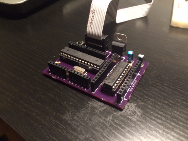
DIY Arduino Board Compatible with 5v and 3.3v
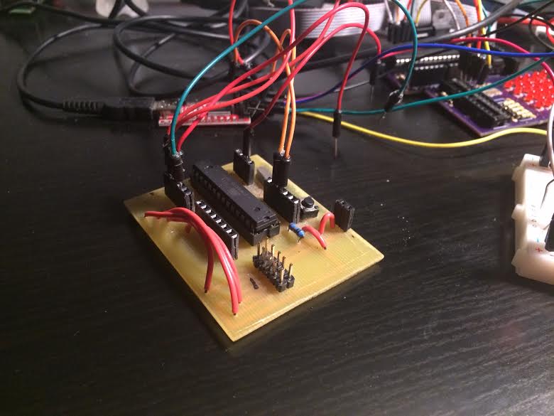
A long time ago I created a breakout board for an ATmega328p to prototype some projects, but time has not been too kind with it. It was hastily made on a single sided homemade PCB, has lots of jumper wires and some of the pins no longer work, probably because my soldering job wasn’t too great. After getting tired of these issues and having to put up with different voltages for different components, I decided to create a better board that can work with both 3.3v and 5v.
Design
The ATmega328p chip is only rated up to 8MHz for 3.3v, so makes sense to run it at 5v and convert the output down to 3.3v to run it at 16MHz. The idea then is to find a chip that you can easily connect outpins to and then have the signals converted to 3.3v.
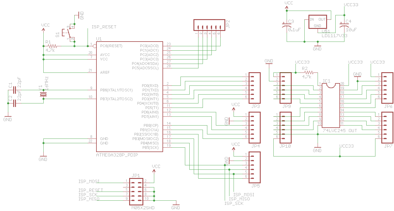
I’m not too fond of SMT parts since they require patience and time to put together, of which I have neither at the moment. So I looked around and found this 74LVC245 IC that is fast enough to convert voltages to use UART and SPI. 5v signals go in one end and 3.3v come out the other side. Perfect. Conversion from 3.3v to 5v isn’t necessary since the ATmega will read them just fine. Probably. And off to Eagle CAD we go.
I use a USBasp Programmer that I bought off eBay to program my AVR chips (JP1). If you want to do that as well, be sure to buy one thats programmed already, if not you’ll end up with a chicken and egg problem where you need a programmer to program the firmware to your programmer (learned the hard way). The USBasp provides 5v from the USB port and then a LD1117v33 (U$1) is used to provide the 3.3v we need for the 74LVC245 chip. Note that the pins are wired incorrectly for the LD1117V33 in the schematic because I used the footprint for another similiar chip that I was too lazy to edit. When designing the schematic, the typical applications section from the data sheets of each chip are quite helpful. They sometimes have an example of exactly what you are trying to do
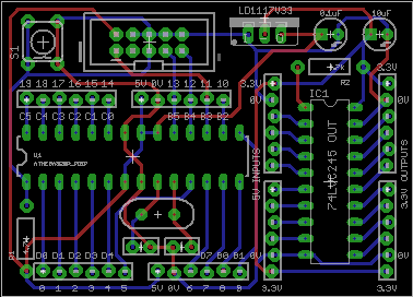
And then came the somewhat tedious and boring part; lots of trial and error for placing the components and routing the board efficiently. I tried my best to keep the size of the PCB small to decrease cost, but it ended up being only slightly smaller than an Arduino due to not using SMT components. I also added labels for both Arduino pin numbers and the traditional ATmega pin names, as sometimes I need both. Parts and boards were ordered off Digi-key and OSH Park respectively.
Result
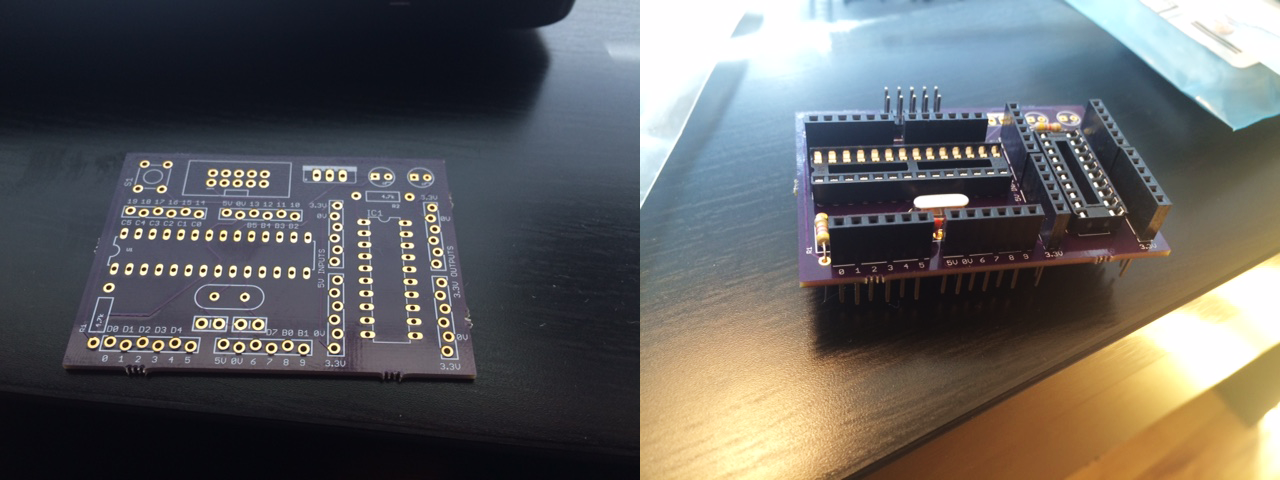
Took a whole afternoon to solder everything together but it turned out great. The onboard 5v to 3.3v conversion works fantastic, beats having to constantly switch the power supply to the ATmega. It is a perfect replacement for the old board. Now I just need projects ideas to use it…
